The Flexible and Interoperable Data Transfer (FIT) protocol is a format designed specifically for the storing and sharing of data that originates from sport, fitness and health devices. It is specifically designed to be compact, interoperable and extensible. This section describes the FIT file structure and interpretation.
The FIT protocol defines a set of data storage templates (FIT messages) that can be used to store information such as user profiles and activity data in files. Any FIT-compliant device can interpret a FIT file from any other FIT-compliant device. A software development kit (SDK) is available for download to generate code and libraries specific to a product’s requirements. The SDK enables efficient use of a binary format at the embedded level, to significantly reduce the development effort and allow for rapid product development.
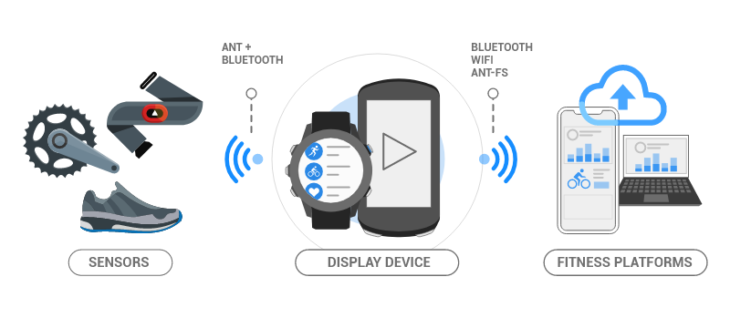
The following example use case illustrates one way that the FIT protocol is used to transfer activity data acquired during exercise to a fitness platform. (Figure 1):
The FIT data may be used directly on the PC or transferred to internet applications
After the initial wireless sensor data is collected, the FIT protocol provides a consistent format allowing all devices in the subsequent chain to share and use the data.
The FIT file protocol was designed to provide:
The FIT file protocol consists of:
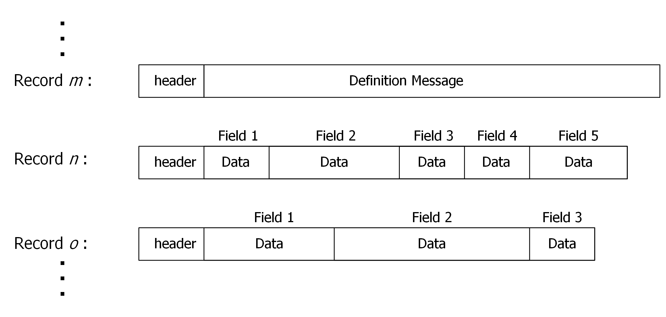
A FIT file contains a series of records that, in turn, contain a header and content. The record content is either a definition message that is used to specify upcoming data, or a data message that contains a series of data-filled fields (Figure 2). The FIT protocol defines the type and content of messages, the data format of each message’s field, and methods of compressing data (if applicable).
There are two types of FIT profiles: global and product. All available FIT messages are outlined in the Global FIT Profile. This is then broken down into smaller subset, Product Profiles, outlining product-specific FIT messages (Figure 3).
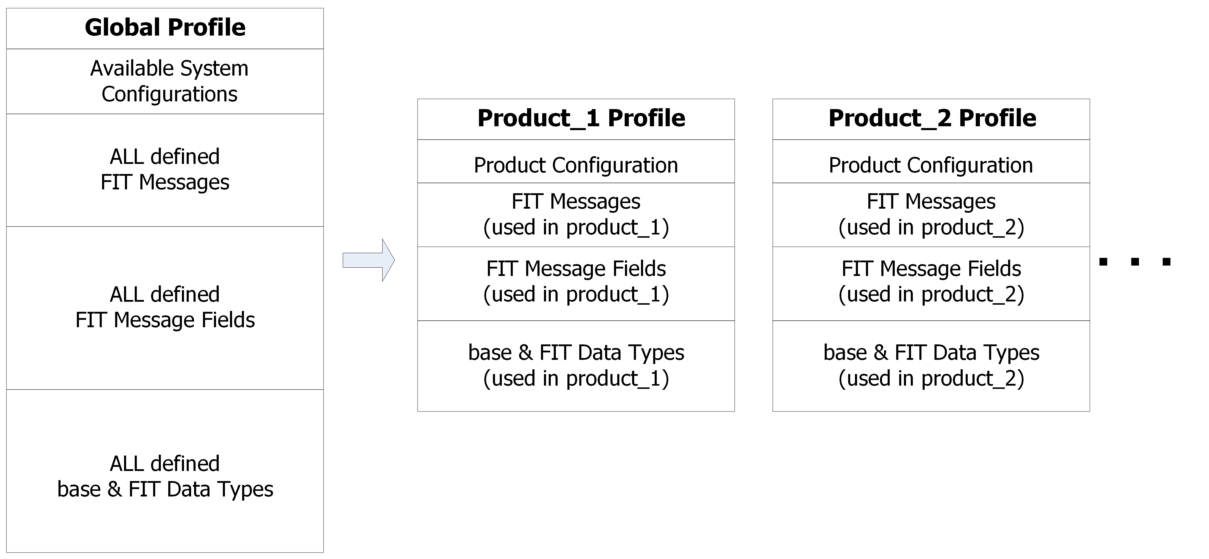
Each profile consists of system configuration information, defined FIT messages and fields, base data types, and FIT data types (Figure 3).
The Global FIT Profile is maintained by Garmin International, Inc. and consists of the complete collection of available system configurations, FIT messages, fields, and data types as described below:
New configurations, messages, and data types may be added as new versions of the SDK are released. Users should not modify existing definitions found in the global profile. Additions may be requested by contacting Garmin International, Inc. at www.thisisant.com.
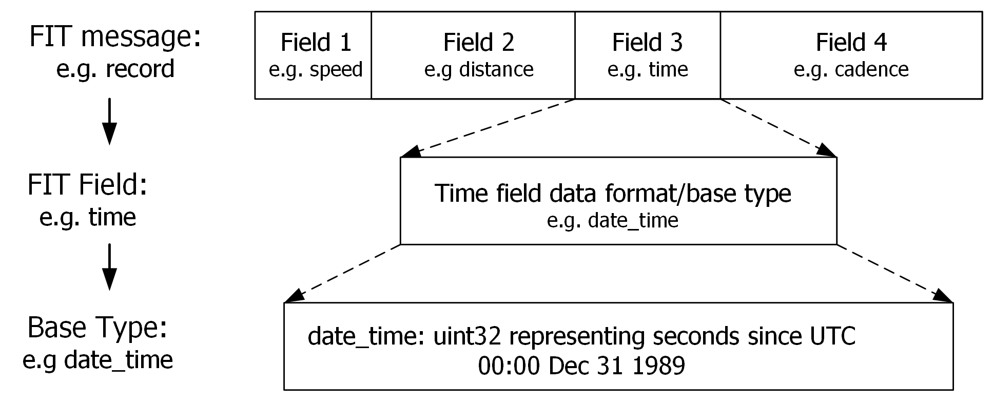
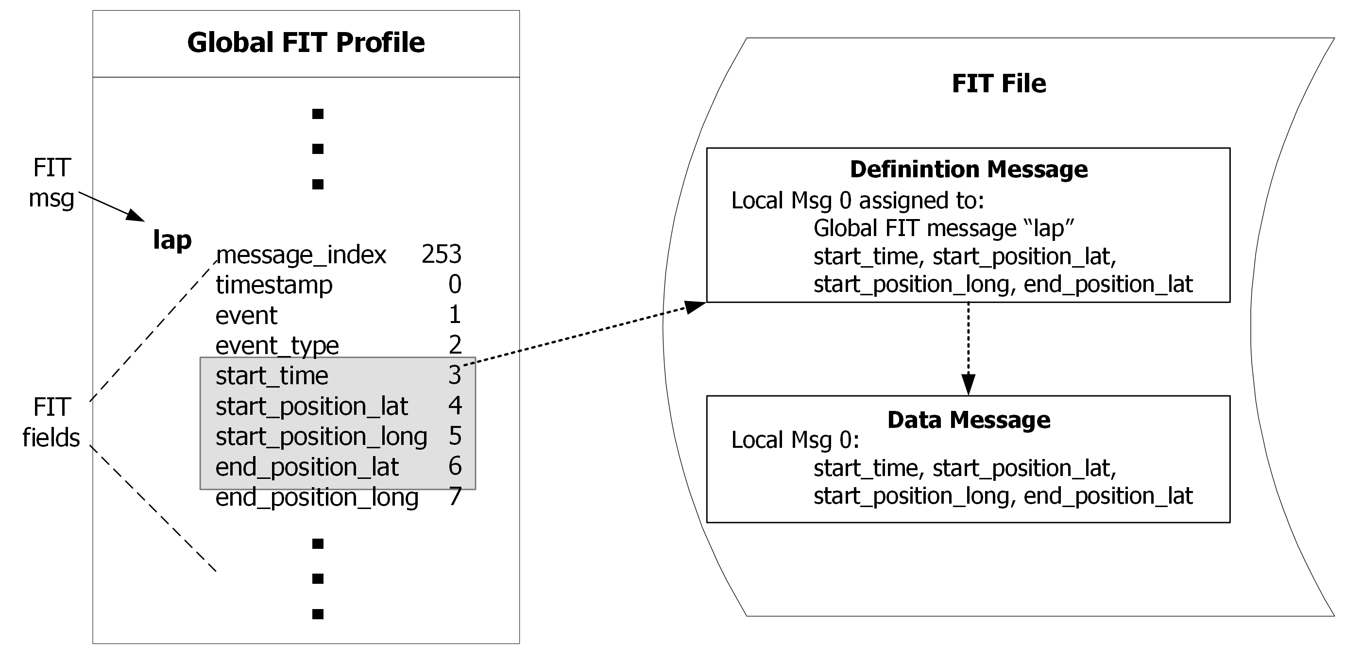
The relationships between FIT messages, fields, and base types are illustrated in Figure 4.
Not all messages defined in the global FIT profile will be relevant to a particular application. A Product Profile is an application specific subset of the Global Profile that defines only the necessary data messages in the configuration of the product’s architecture (Figure 3). An SDK is available to allow the developer to select the desired system configuration and relevant data messages and then generate application specific FIT code.
Custom messages may be defined in the manufacturer specific message range (0xFF00–0xFFFE). Information contained in manufacturer specific messages will generally not be interoperable, since other applications will not have knowledge of them.
Two different FIT devices may use different product profiles or versions of the complete Global Profile. This may result in one device receiving a FIT message that it does not recognize. When this occurs, the FIT file is maintained in its entirety and any unrecognized messages are simply ignored by the decoder without interrupting the operation of the receiving device, or causing any errors. Similarly, if a device does not receive data that it may expect, it will simply fill those fields with an invalid value rather than creating errors. In this way, the FIT protocol will ensure compatibility across devices that may not have the exact same profiles implemented. These compatibility processes are discussed in more detail in later sections.
The FIT protocol defines the process for which profiles are implemented and files are transferred. Figure 5 provides an overview of the FIT process. Typically, ANT+ broadcast data is collected by a display device. The display device would then encode the data into the FIT file format according to its product profile (i.e. product profile 1). The FIT file is then transferred to another device which would then decode the received files according to its own implemented product profile (i.e. product profile 2).
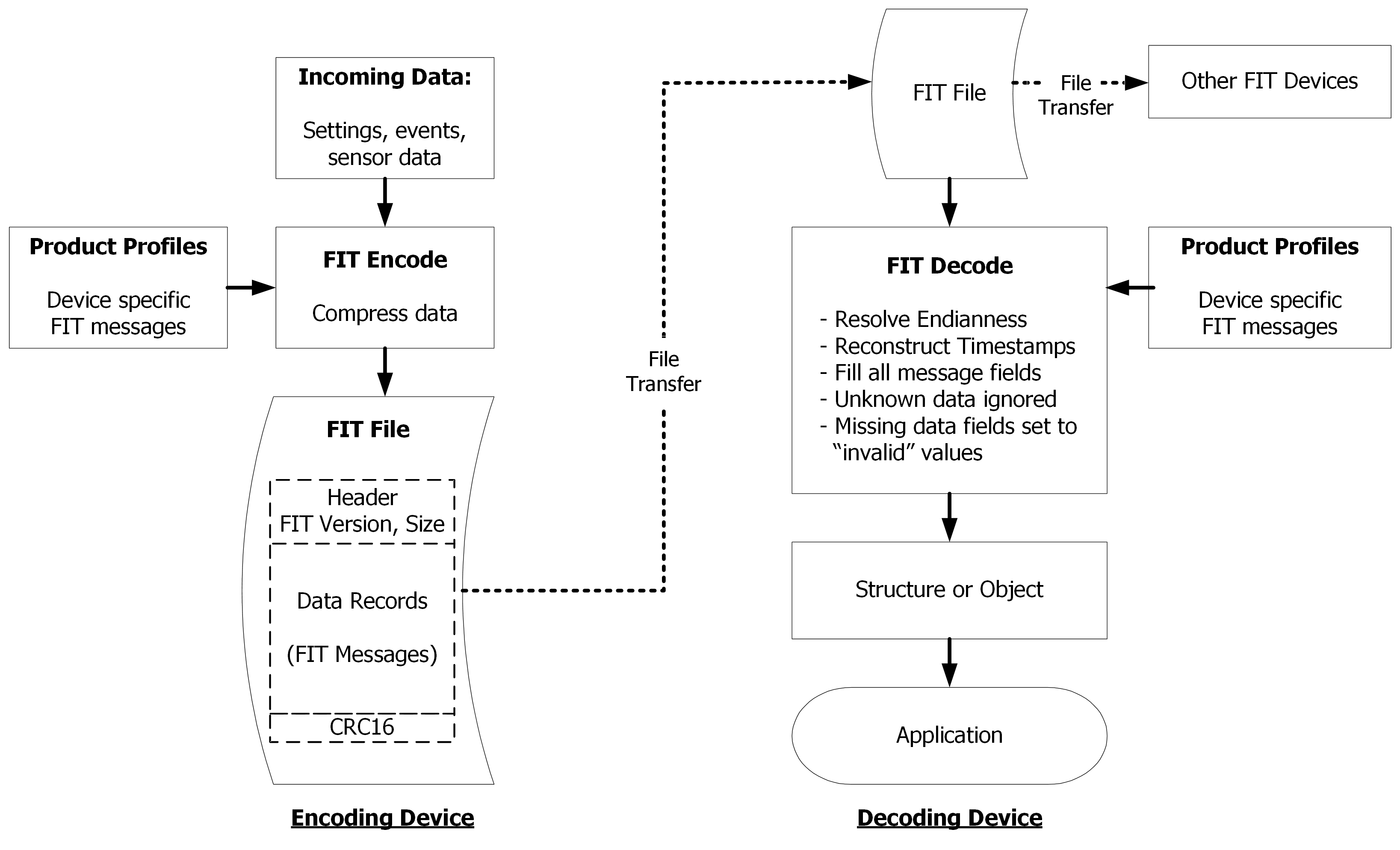
Incoming data such as settings, events and sensor data are written into FIT message fields according to the formats defined by the device’s product profiles. The FIT encoding process is optimized, such that only valid fields are written to the file. The file can then be transferred to another FIT device. When the data is used by the receiving device, it is decoded according to its implemented product profiles, which relate the received FIT messages to the global FIT message list. The decoded values will then be passed as structures or objects to the application.
The SDK code will resolve native endianness, reconstruct timestamp information and fill all message fields appropriately. If there is a difference in profile version between the two devices, any missing data will be set to invalid or default values as defined in the FIT protocol, and any unknown messages or data will be ignored. The FIT file is maintained in its original form for transfer to other devices, if desired.
All FIT files have the same structure which consists of a File Header, a main Data Records section that contains the encoded FIT messages, followed by a 2 byte CRC (Figure 6.a).
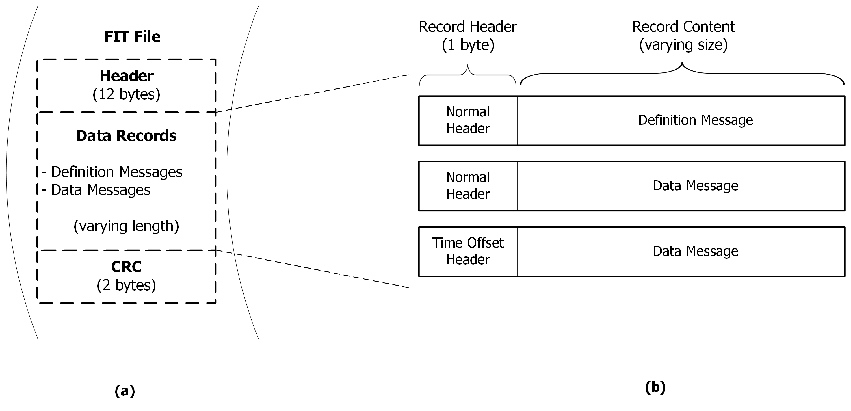
The file header provides information about the FIT File. The minimum size of the file header is 12 bytes including protocol and profile version numbers, the amount of data contained in the file and data type signature. The 12 byte header is considered legacy, using the 14 byte header is preferred. The header size should always be decoded before attempting to interpret a FIT file, Garmin International, Inc. may extend the header as necessary. Computing the CRC is optional when using a 14 byte file header, it is permissible to set it to 0x0000. Including the CRC in the file header allows the CRC of the file to be computed as the file is being written when the amount of data to be contained in the file is not known. Table 1 outlines the FIT file header format.
Table 1. Byte Description of File Header
| Byte | Parameter | Size (Bytes) | Description |
|---|---|---|---|
| 0 | Header Size | 1 | Indicates the length of this file header including header size. Minimum size is 12. This may be increased in future to add additional optional information |
| 1 | Protocol Version | 1 | Protocol version number as provided in SDK |
| 2 | Profile Version LSB | 2 | Profile version number as provided in SDK |
| 3 | Profile Version MSB | ||
| 4 | Data Size LSB | 4 | Length of the Data Records section in bytesDoes not include Header or CRC |
| 5 | Data Size | ||
| 6 | Data Size | ||
| 7 | Data Size MSB | ||
| 8 | Data Type Byte[0] | 4 | ASCII values for “.FIT”. A FIT binary file opened with a text editor will contain a readable “.FIT” in the first line. |
| 9 | Data Type Byte[1] | ||
| 10 | Data Type Byte[2] | ||
| 11 | Data Type Byte[3] | ||
| 12 | CRC LSB | 2 | Contains the value of the CRC (see CRC ) of Bytes 0 through 11, or may be set to 0x0000. This field is optional. |
| 13 | CRC MSB |
The final 2 bytes of a FIT file contain a 16 bit CRC in little endian format. The CRC is computed as follows:
FIT_UINT16 FitCRC_Get16(FIT_UINT16 crc, FIT_UINT8 byte)
{
   static const FIT_UINT16 crc_table[16] =
   {
      0x0000, 0xCC01, 0xD801, 0x1400, 0xF001, 0x3C00, 0x2800, 0xE401,
      0xA001, 0x6C00, 0x7800, 0xB401, 0x5000, 0x9C01, 0x8801, 0x4400
   };
   FIT_UINT16 tmp;

   // compute checksum of lower four bits of byte
   tmp = crc_table[crc & 0xF];
   crc = (crc >> 4) & 0x0FFF;
   crc = crc ^ tmp ^ crc_table[byte & 0xF];

   // now compute checksum of upper four bits of byte
   tmp = crc_table[crc & 0xF];
   crc = (crc >> 4) & 0x0FFF;
   crc = crc ^ tmp ^ crc_table[(byte >> 4) & 0xF];

   return crc;
}
The data records in the FIT file are the main content and purpose of the FIT protocol. There are two kinds of data records:
Definition Messages: these define the upcoming data messages. A definition message will define a local message type and associate it to a specific FIT message, and then designate the byte alignment and field contents of the upcoming data message.
Data Messages: these contain a local message type and populated data fields in the format described by the preceding definition message. The definition message and its associated data messages will have matching local message types. There are two types of data message:
These messages will be further explained in the Record Format section. All records contain a 1 byte Record Header that indicates whether the Record Content is a definition message, a normal data message or a compressed timestamp data message (Figure 6.b). The lengths of the records vary in size depending on the number and size of fields within them.
All data messages are handled locally, and the definition messages are used to associate local data message types to the global FIT message profile. For example, a definition message may specify that data messages of local message type 0 are Global FIT ‘lap’ messages (Figure 7). The definition message also specifies which of the ‘lap’ fields are included in the data messages (start_time, start_position_lat, start_position_long, end_position_lat, end_position_long), and the format of the data in those fields. As a result, data messages can be optimized to contain only data, and the local message type is referenced in the header. Data messages are referenced to local message type.
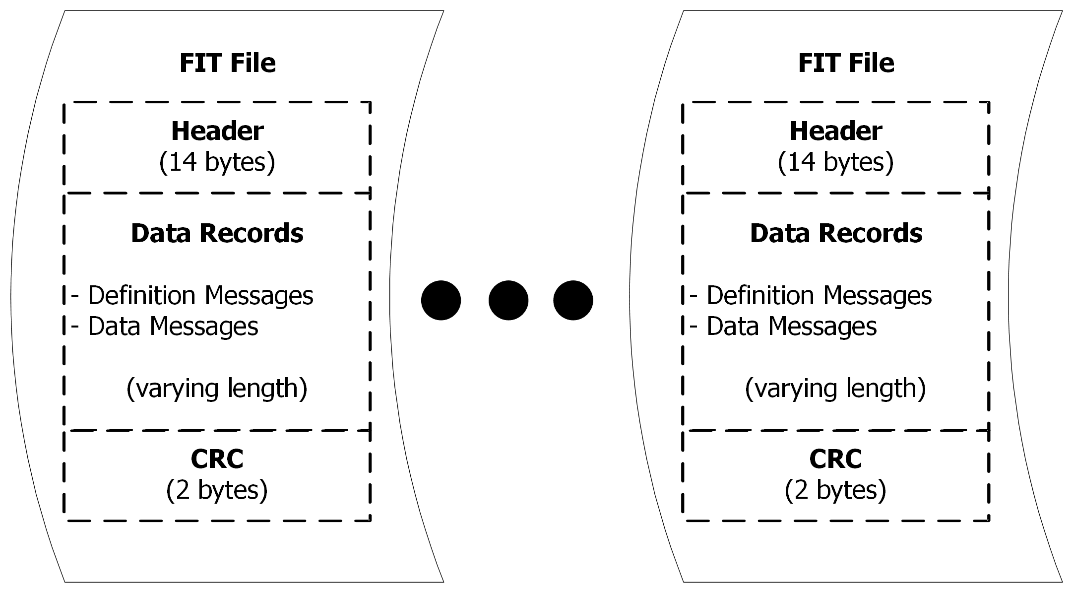
The FIT protocol allows for multiple FIT files to be chained together in a single FIT file. Each FIT file in the chain must be a properly formatted FIT file (header, data records, CRC).
A FIT record consists of two parts: a Record Header and the Record Content. The record header indicates whether the record content contains a definition message, a normal data message or a compressed timestamp data message. The record header also has a Local Message Type field that references the local message in the data record to its global FIT message.
The Record Header is a one byte bit field. There are actually two types of record headers: normal header and compressed timestamp header. The header type is indicated in the most significant bit (msb) of the record header. The normal header identifies whether the record is a definition or data message, and identifies the local message type. A compressed timestamp header is a special compressed header that may also be used with some local data messages to allow a compressed time format.
A value of 0 in Bit 7 of the record header indicates that this is a Normal Header. The bit field description for a normal header is shown below in Table 2.
Table 2. Normal Header Bit Field Description
| Bit | Value | Description |
|---|---|---|
| 7 | 0 | Normal Header |
| 6 | 0 or 1 | Message Type 1: Definition Message 0: Data Message |
| 5 | 0 (default) | Message Type Specific |
| 4 | 0 | Reserved |
| 0 - 3 | 0 - 15 | Local Message Type |
The message type indicates whether the record contains a definition or data message.
The value in bit 5 of a normal header changes based on if we are writing a Definition or Data Message
If the bit is set the message contains extended definitions for developer data. The details of developer data are highlighted in 4.2.1.5.
Reserved in data messages and should be set to 0.
The Local Message Type is used to create an association between the definition message, data message and the FIT message in the Global FIT Profile.
Definition Message : In a definition message, the local message type is assigned to a Global FIT Message Number (mesg_num) relating the local messages to their respective FIT messages
Data Message : The local message type associates a data message to its respective definition message, and hence, its' global FIT message. A data message will follow the format as specified in its definition message of matching local message type.
Local Message Types can be redefined within a single FIT file, please refer to Redefining Local Message Types for best practices when using a single local message type for different records.
Example:
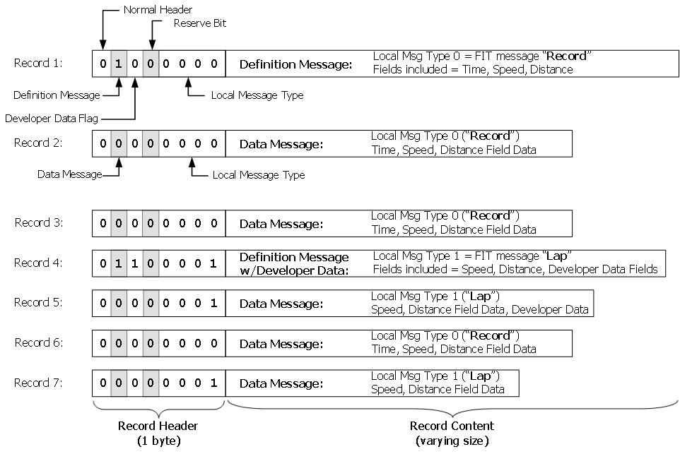
Figure 9 shows an example of using data records with normal headers to designate definition and respective data messages for recording FIT ‘record’ and ‘lap’ messages.
The compressed timestamp header is a special form of record header that allows some timestamp information to be placed within the record header, rather than within the record content. In applicable use cases, this allows data to be recorded without the need of a 4 byte timestamp in every data record. The bit field description of a compressed timestamp header is shown in Table 3 below.
Table 3. Compressed Timestamp Header Bit Field Description
| Bit | Value | Description |
|---|---|---|
| 7 | 1 | Compressed Timestamp Header |
| 5 – 6 | 0 - 3 | Local Message Type |
| 0 - 4 | 0 - 31 | Time Offset (seconds) |
Note this type of record header is used for a data message only.
In order to compress the header, only 2 bits are allocated for the local message type. As a result, the use of this special header is restricted to local message types 0–3, and cannot be used for local message types 4–15. The local message type can be redefined within a single FIT file, please refer to Redefining Local Message Types for more details.
The five least significant bits (lsb) of the header represent the compressed timestamp, in seconds, from a fixed time reference. The time resolution is not configurable. The fixed time reference is provided in the form of any FIT message containing a full, four byte timestamp recorded prior to the use of the compressed timestamp header (see example). The 5-bit time offset rolls over every 32 seconds; hence, it is necessary that any two consecutive compressed timestamp records be measured less than 32 seconds apart.
The actual timestamp value is determined by concatenating the most significant 27 bits of the previous timestamp value and the 5 bit value of the time offset field. Rollover must be taken into account such that:
If Time Offset >= (Previous Timestamp)&0x0000001F (i.e. offset value is greater than least significant 5 bits of previous timestamp):
Timestamp = (Previous timestamp) & 0xFFFFFFE0 + Time Offset
If Time Offset < (Previous Timestamp) & 0x0000001F (i.e. offset is less than least significant 5 bits of previous timestamp):
Timestamp = (Previous timestamp) & 0xFFFFFFE0 + Time Offset + 0x20
The addition of 0x20 accounts for the rollover event
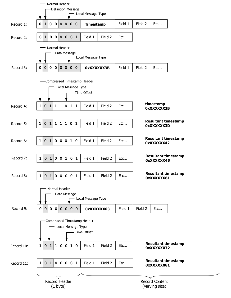
Refer to Figure 10 for an example of using compressed timestamp headers. In this example, local message type 0 is used to define a message containing a both a timestamp field and multiple data fields (Record 1). Local message type 1 defines a message containing only data fields (Record 2).
Record 3 is a data message which includes a timestamp value of 0xXXXXXX3B. For the purpose of this example, the values of the upper 3 bytes do not change and are set as 0xXX ‘don’t care’ values.
Record 4 is a data message using a compressed timestamp header. As the Time Offset value is the same as the 5 least significant bits of the previous timestamp, the calculated timestamp for record 4 is 0xXXXXXX3B.
Record 5 is another data message using a compressed timestamp header. The Time Offset value is greater than the 5 least significant bits of the previous timestamp by 2 seconds, so the calculated timestamp for record 5 becomes 0xXXXXXX3D.
Record 6 Time Offset value is 00010, which is smaller than the 5 least significant bits of the previous timestamp (5 lsb of 0xXXXXXX3D is 11101), indicating a rollover event has occurred. Therefore, the timestamp becomes 0xXXXXXX42.
Similarly, record 7 shows an increase in time of 3 seconds and the timestamp becomes 0xXXXXXX45, and record 8 shows a rollover event resulting in a timestamp of 0xXXXXXX61.
Finally, if a new data message containing a timestamp is recorded (i.e. record 9), then this becomes the new time reference for any subsequent compressed timestamp data records, such as records 10 and 11.
The record content contains one of two messages:
Definition and data messages are associated through the local message type. A data message must always be specified by a definition message before it can be used in a FIT file. If a data message is sent without first being defined, it will cause a decode error and the data will not be interpreted. Definition messages are used by the conversion tools to interpret subsequent data messages contained in a FIT file. For more details see Best Practices
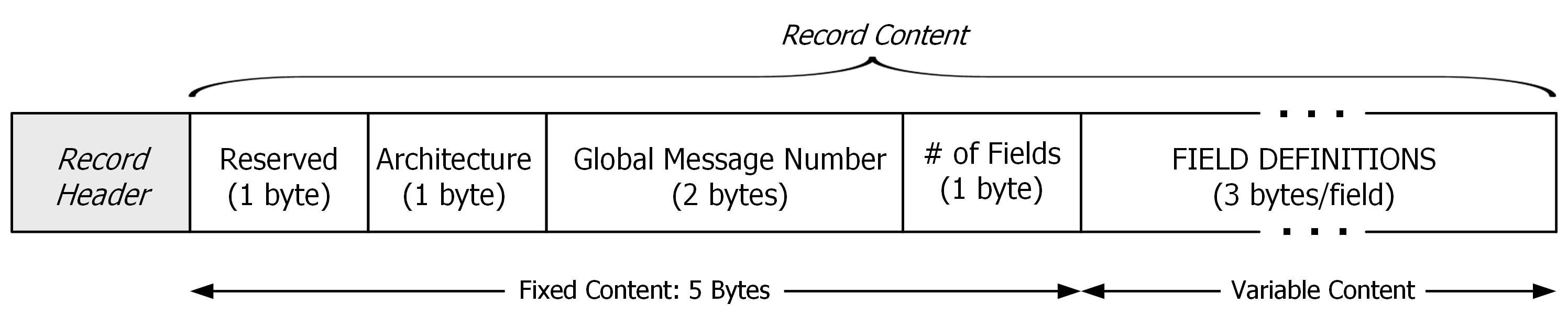
The definition message is used to create an association between the local message type contained in the record header, and a Global Message Number (mesg_num) that relates to the global FIT message.

Definition messages are extended to include additional Developer Field Definitions if the Developer Data flag is set in the record header.
The record contents of a definition message are outlined in Table 4 below.
Table 4. Definition Message Contents
| Byte | Description | Length | Value |
|---|---|---|---|
| 0 | Reserved | 1 Byte | 0 |
| 1 | Architecture | 1 Byte | Architecture Type 0: Definition and Data Messages are Little Endian 1: Definition and Data Message are Big Endian |
| 2–3 | Global Message Number | 2 Bytes | 0:65535 – Unique to each message *Endianness of this 2 Byte value is defined in the Architecture byte |
| 4 | Fields | 1 Byte | Number of fields in the Data Message |
| 5 –4 + Fields * 3 | Field Definition | 3 Bytes (per Field) | See Field Definition Contents (Table 5) |
| 5 + Fields * 3 | # Developer Fields | 1 Byte | Number of Self Descriptive fields in the Data Message(Only if Developer Data Flag is set) |
| 6 + Fields * 3 - END | Developer Field Definition | 3 bytes (per Field) | See Developer Data Field Definition Contents (Table 8) |
The Architecture Type describes whether the system architecture is big or little endian. All data in the related definition and upcoming data message will follow this format.
The Global Message Number relates to the Global FIT Message. For example, the Global FIT Message ‘Record’ has the global message number ‘20’. All Global Message Numbers are found in the mesg_num base type defined in the SDK.
Fields defines the number of FIT fields that will be included in the data message. For example, if a given FIT message had 10 defined FIT fields, the application may only choose to send 4 of those FIT fields in the data message. In this case, the Fields byte would be set to ‘4’. All FIT messages and their respective fields are listed in the global FIT profile.
The Field Definition bytes are used to specify which FIT fields of the global FIT message are to be included in the upcoming data message in this instance. Any subsequent data messages of a particular local message type are considered to be using the format described by the definition message of matching local message type. All FIT messages and their respective FIT fields are listed in the global FIT profile. Each Field Definition consists of 3 bytes as detailed in Table 5. Refer to Figure 14 for an example definition message.
Table 5. Field Definition Contents
| Byte | Name | Description |
|---|---|---|
| 0 | Field Definition Number | Defined in the Global FIT profile for the specified FIT message |
| 1 | Size | Size (in bytes) of the specified FIT message’s field |
| 2 | Base Type | Base type of the specified FIT message’s field |
The Field Definition Number uniquely identifies a specific FIT field of the given FIT message. The field definition numbers for each global FIT message are provided in the SDK. 255 represents an invalid field number.
The Size indicates the size of the defined field in bytes. The size may be a multiple of the underlying FIT Base Type size indicating the field contains multiple elements represented as an array.
Base Type describes the FIT field as a specific type of FIT variable (unsigned char, signed short, etc). This allows the FIT decoder to appropriately handle invalid or unknown data of this type. The format of the base type bit field is shown below in Table 6. All available Base Types are fully defined in the fit.h file included in the SDK.
Table 6. Definition Message Contents
| Bit | Name | Description |
|---|---|---|
| 7 | Endian Ability | 0 - for single byte data 1 - if base type has endianness (i.e. base type is 2 or more bytes) |
| 5–6 | Reserved | Reserved |
| 0–4 | Base Type Number | Number assigned to Base Type (provided in SDK) |
When the decoder encounters unknown or invalid data, it will assign an invalid value according to the designated base type. Base type numbers (bits 0:4) and their invalid values can also be found in the fit.h file provided in the SDK and as listed in Table 7 below.
Table 7. FIT Base Types and Invalid Values
| Base Type # | Endian Ability | Base Type Field | Type Name | Invalid Value | Size (Bytes) | Comment |
|---|---|---|---|---|---|---|
| 0 | 0 | 0x00 | enum | 0xFF | 1 | |
| 1 | 0 | 0x01 | sint8 | 0x7F | 1 | 2’s complement format |
| 2 | 0 | 0x02 | uint8 | 0xFF | 1 | |
| 3 | 1 | 0x83 | sint16 | 0x7FFF | 2 | 2’s complement format |
| 4 | 1 | 0x84 | uint16 | 0xFFFF | 2 | |
| 5 | 1 | 0x85 | sint32 | 0x7FFFFFFF | 4 | 2’s complement format |
| 6 | 1 | 0x86 | uint32 | 0xFFFFFFFF | 4 | |
| 7 | 0 | 0x07 | string | 0x00 | 1 | Null terminated string encoded in UTF-8 format |
| 8 | 1 | 0x88 | float32 | 0xFFFFFFFF | 4 | |
| 9 | 1 | 0x89 | float64 | 0xFFFFFFFFFFFFFFFF | 8 | |
| 10 | 0 | 0x0A | uint8z | 0x00 | 1 | |
| 11 | 1 | 0x8B | uint16z | 0x0000 | 2 | |
| 12 | 1 | 0x8C | uint32z | 0x00000000 | 4 | |
| 13 | 0 | 0x0D | byte | 0xFF | 1 | Array of bytes. Field is invalid if all bytes are invalid. |
| 14 | 1 | 0x8E | sint64 | 0x7FFFFFFFFFFFFFFF | 8 | 2’s complement format |
| 15 | 1 | 0x8F | uint64 | 0xFFFFFFFFFFFFFFFF | 8 | |
| 16 | 1 | 0x90 | uint64z | 0x0000000000000000 | 8 |
Developer data fields allow for files to define the meaning of data without requiring changes to the FIT profile being used. Rather than having information like Field Name, Units, and Base Type encoded into the profile this information is included in 2 special global messages that act as meta-data for the decode process. The developer data field description is used to map data within a data message to the appropriate meta-data.
Table 8 – Developer Field Description
| Byte | Name | Description |
|---|---|---|
| 0 | Field Number | Maps to the field_definition_number of a field_description Message |
| 1 | Size | Size (in bytes) of the specified FIT message’s field |
| 2 | Developer Data Index | Maps to the developer_data_index of a developer_data_id Message |
Developer data ID messages are used to uniquely identify developer data field sources, a FIT file can contain data for up to 255 unique developers. These messages must occur before any related field description messages.
Table 9 - Developer Data ID Message
| Name | Type | Size | Description |
|---|---|---|---|
| application_id | uint8 | 16 | 16-byte identifier for the developer |
| developer_data_index | uint8 | 1 | Developer Data Index that maps to this Message. |
Field description messages define the meaning of data within a dev field, a FIT file can contain up to 255 unique fields per developer. These messages must occur in the file before any related data is added.
Table 10 - Field Description Messages
| Name | Type | Size | Description |
|---|---|---|---|
| developer_data_index | uint8 | 1 | Index of the developer that this message maps to |
| field_definition_number | uint8 | 1 | Field Number that maps to this message |
| fit_base_type_id | uint8 | 1 | Base type of the field |
| field_name | string | 64 | Name of the field |
| units | string | 16 | Units associated with the field |
| native_field_num | uint8 | 1 | Equivalent native field number |
The native_field_num field is used to indicate that a field can be considered equivalent to the corresponding field_number in the message that the developer data is included in. This field can be used to indicate to data consumers that the developer considers its data to be the same as native data.
Developer Fields that override native FIT fields shall preserve the units defined for that field in the Profile.xlsx document. Scaling and offset defined in Profile.xlsx for the native data fields shall not be applied to the developer data field. Instead, the developer data field shall be logged with full precision and resolution using the appropriate base data type.
For example, if overriding total_hemoglobin_conc in the record message, which has a scaling of 100, the developer data field should be logged as a float (to keep two decimal places of precision).
Developer fields will be written to the FIT file in such a way that decoders do not need to manipulate them in any way. Decoders that are consuming developer data should not trust that developer data is logged correctly. It is still strongly recommended to do some basic data verification before attempting to display it.
Once a global FIT message has been associated to a local message type, and the format of the FIT fields defined, data messages may be written to the FIT file. Definition messages have a minimum length of 8 bytes, excluding the record header; however, data messages can be very compact.
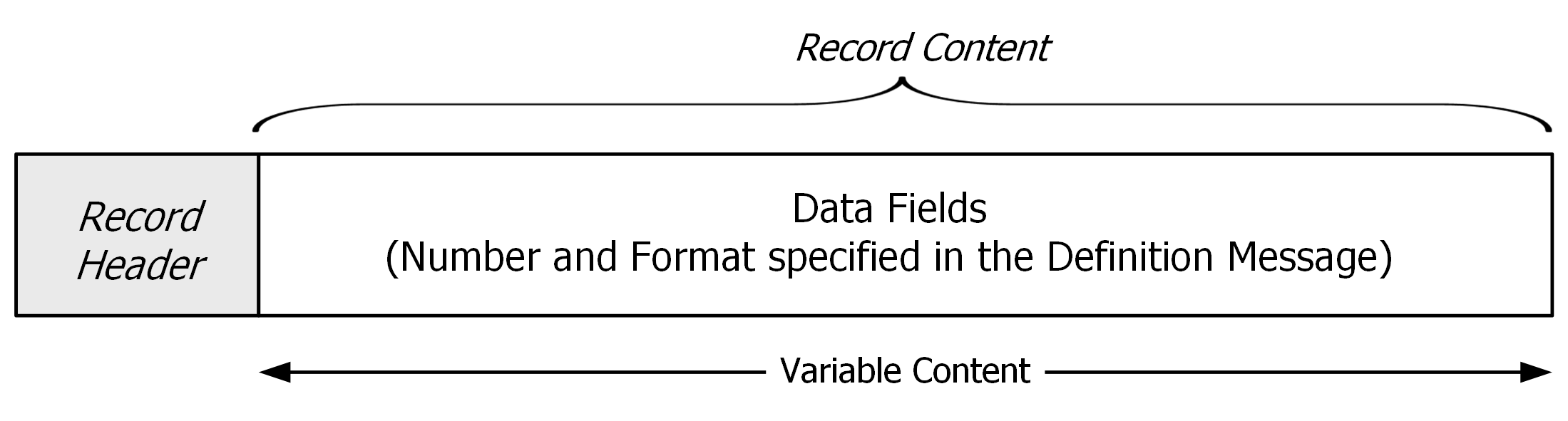
A data message must start with a normal or compressed timestamp header indicating its local message type, and the record content must be formatted according to the definition message of matching local message type.
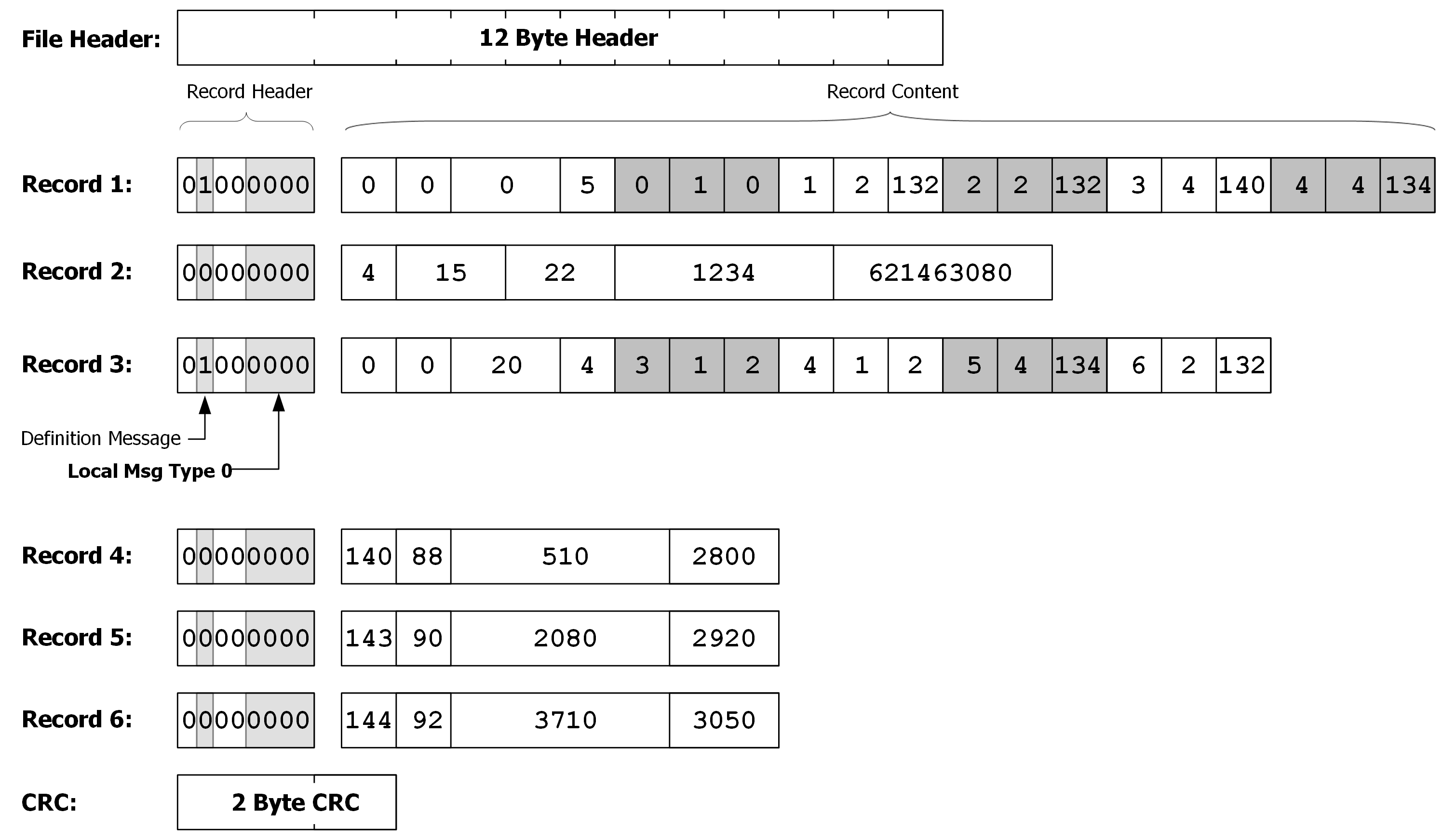
The example FIT file in Figure 14 shows a simple FIT Activity file containing the 14-byte file header, data records, custom developer data and 2 byte CRC.
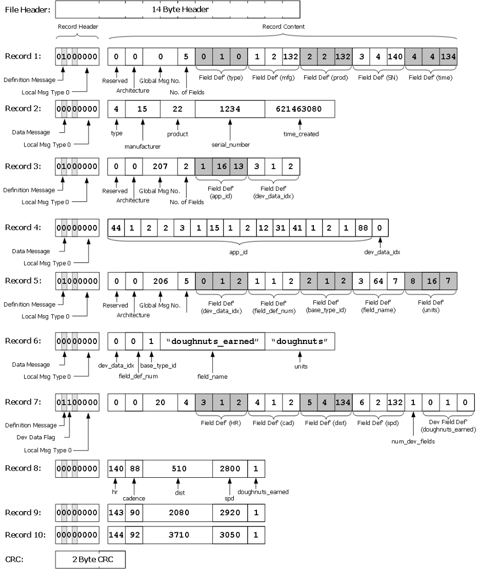
Indicates the record is a definition message specifying the upcoming data messages (of local message type 0) are:
Little Endian
Global Message Number 0 identifies FIT ‘file_id’ message
The FIT file_id fields that will be included in the associated data message are:
Field Definition Number: 0 (type); Size: 1 byte; Base Type: 0 (enum)
Field Definition Number: 1 (manufacturer); Size: 2 bytes; Base Type: 132 (uint16)
Field Definition Number: 2 (product); Size: 2 bytes; Base Type: 132 (uint16)
Field Definition Number: 3 (serial number); Size: 4 bytes; Base Type: 140 (uint32z)
Field Definition Number: 4 (time_created); Size: 4 bytes; Base Type: 134 (uint32)
Global Message Number is found in the mesg_num type of the FIT protocol.
Field Definition Numbers for each FIT message are found in the FIT profile provided in the SDK. Size and Base Type definitions are located in the fit.h file in the SDK, or as listed in Table 7 below.
Indicates the record is a data message of local message type 0. Data is formatted according to the definition message of local message type 0:
Little Endian, FIT ‘file_id’ message
Included Fields and Data:
type: 4* (activity file)
manufacturer: 15* (Dynastream)
product: 22
serial number: 1234
time_created: 621463080 (14 Aug 2009)
* These values are defined in the FIT protocol
Indicates the record is a definition message specifying the upcoming data messages (of local message type 0) are:
Little Endian
Global Message Number 207 identifies FIT ‘dev_data_id’ message
The FIT file_id fields that will be included in the associated data message are:
Field Definition Number: 1 (app_id); Size: 16 bytes; Base Type: 13 (byte)
Field Definition Number: 3 (dev_data_index); Size: 1 byte; Base Type: 2 (uint8)
Indicates the record is a data message of local message type 0. Data is formatted according to the definition message of local message type 0:
Little Endian, FIT ‘dev_data_id’ message
Included Fields and Data:
app_id: [44, 1, 22, 2, 3, 1, 15, 1, 2, 12, 31, 41, 1, 2, 1, 88, 12, 13, 12, 22]
dev_data_idx: 0
Indicates the record is a definition message specifying the upcoming data messages (of local message type 0) are:
Little Endian
Global Message Number 206 identifies FIT ‘field_description’ message
The FIT file_id fields that will be included in the associated data message are:
Field Definition Number: 0 (dev_data_idx); Size: 1 byte; Base Type: 2 (uint8)
Field Definition Number: 1 (field_def_num); Size: 1 byte; Base Type: 2 (uint8)
Field Definition Number: 2 (base_type_id); Size: 1 byte; Base Type: 2 (uint8)
Field Definition Number: 3 (field_name); Size: 64 byte; Base Type: 7 (string)
Field Definition Number: 8 (units); Size: 16 byte; Base Type: 7 (string)
Indicates the record is a data message of local message type 0. Data is formatted according to the definition message of local message type 0:
Little Endian, FIT ‘field_description’ message
Included Fields and Data:
dev_data_idx: 0
field_def_num: 0
base_type_id: 1 (sint8)
field_name: "doughnuts_earned"
units: "doughnuts"
Indicates the record is a definition message specifying the upcoming data messages (of local message type 0) are:
Little Endian
Includes Custom Developer Data
Global Message Number 20 identifies FIT ‘record’ message
The FIT record fields that will be included in the associated data message are:
Field Definition Number: 3 (heart_rate); Size: 1 byte; Base Type: 2 (uint8)
Field Definition Number: 4 (cadence); Size: 1 bytes; Base Type: 2 (uint8)
Field Definition Number: 5 (distance); Size: 4 bytes; Base Type: 134 (uint32)
Field Definition Number: 6 (speed); Size: 2 bytes; Base Type: 132 (uint16)
The Developer data that will be included in the associated messages are:
Field Number: 0; Size: 1 bytes; Developer Data Index: 0
Global Message Number is found in the mesg_num type of the FIT protocol.
Field Definition Numbers for each FIT message are found in the FIT profile provided in the SDK. Size and Base Type definitions are located in the fit.h file in the SDK.
Indicates the record is a data message of local message type 0. Data is formatted according to the definition message of local message type 0:
Little Endian, FIT ‘record’ message
Included Fields and Data:
heart_rate : 140 (bpm)
cadence: 88 (rpm)
distance: 510 (cm)
speed: 2800 (mm/s)
doughnuts_earned: 1 (doughnut)
Indicates the record is a data message of local message type 0. Data is formatted according to the definition message of local message type 0:
Little Endian, FIT ‘record’ message
Included Fields and Data:
heart_rate : 143 (bpm)
cadence: 90 (rpm)
distance: 2080 (cm)
speed: 2920 (mm/s)
doughnuts_earned: 1 (doughnut)
Indicates the record is a data message of local message type 0. Data is formatted according to the definition message of local message type 0:
Little Endian, FIT ‘record’ message
Included Fields and Data:
heart_rate : 144 (bpm)
cadence: 92 (rpm)
distance: 3710 (cm)
speed: 3050 (mm/s)
doughnuts_earned: 1 (doughnut)
Note that in this example, the fields are defined in the order of increasing field number. This does not have to be the case. Field definitions do not need to be in the order of increasing field number, however, the order the fields are recorded in data message MUST follow the order they are defined in the definition message.
The FIT SDK supports applying a scale or offset to binary fields. This allows efficient representation of values within a particular range and provides a convenient method for representing floating point values in integer systems. A scale or offset may be specified in the FIT profile for binary fields (sint/uint etc.) only. When specified, the binary quantity is divided by the scale factor and then the offset is subtracted, yielding a floating point quantity. The field access functions within the SDK automatically handle this conversion. If no scale and offset are specified, the field is interpreted as the underlying type and no extra conversion is necessary.
Table 11. Example Field Featuring Both Scale and Offset
| Field | Type | Scale | Offset | Units |
|---|---|---|---|---|
| altitude | uint16 | 5 | 500 | m |
Table 12. Altitude Field Value Encoding
| Quantity | Value | Field Value (Decimal) | Field Value (Hex) |
|---|---|---|---|
| Height of Aconcagua | 6960.8m | 37304 | 0x91B8 |
| Minimum Value | -500.0m | 0 | 0x0000 |
| Maximum Value | 12606.8m | 65534 | 0xFFFE |
The interpretation of some message fields depends on the value of another previously defined field. This is called a Dynamic Field. For example, field #3 of the ‘event’ message is ‘data’ and is a dynamic field. If the ‘event’ field is equal to ‘battery’ then ‘data’ is interpreted as ‘battery level’. Similarly, if ‘event’ is ‘fitness_equipment’ then ‘data’ is interpreted as ‘fitness_equipment_state’.
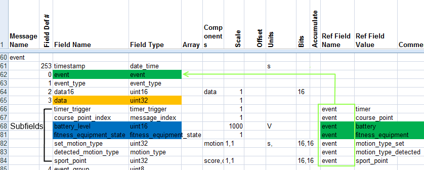
These alternate field interpretations (e.g. ‘battery_level’ and ‘fitness_equipment_state’) are known as subfields and differ somewhat from regular fields. They have no field number (‘Field Def #’ as shown in the figure above); instead, the field number of the main field (e.g. ‘data’) always applies. Subfields must have one or more reference field and reference value combinations. When the reference field contains the reference value, the field shall be interpreted using the properties (name, scale, type etc.) of the subfield rather than the main field. Reference fields must be of integer type, floating point reference values are not supported. If none of the reference field/value combinations are true then the field is interpreted as usual (as ‘data’ in this example). Subfields may be of different type or size so long as each subfield is not larger than the main field. Care must be taken to define reference field/value combinations that are unambiguous for each desired subfield.
Subfields may contain components. The FIT protocol supports nested components meaning subfields may contain components that are also subfields.
The advantage of dynamic fields is that their use allows the interpretation of a field to change, without the usual prerequisite to write a new message definition. This optimizes the size of a file.
Components are a way of compressing one or more fields into a bit field expressed in a single containing field. This can allow some space saving/compression. On decode the SDK will automatically create new field objects and extract the data from the containing field. A destination field of the same name must be defined for every component in the containing field but is not included in the message, it will be automatically generated by the decoder. The destination field can itself contain components requiring expansion.
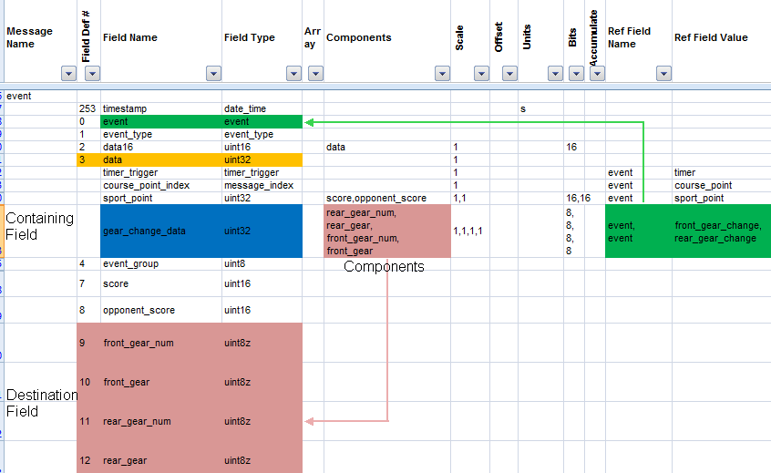
As shown in Figure 16, the subfield ‘gear_change_data’ contains four components (‘rear_gear_num’, ‘rear_gear’, ‘front_gear_num’ and ‘front_gear’). This means when the subfield is encountered in an event message (i.e. if ‘event’ is ‘front_gear_change’ or ‘rear_gear_change’, see Dynamic Fields for discussion of Subfields) the data is expanded into the four destination fields of the same name.
The ‘bits’ property is used to specify the format of the data in the containing field; N bits of data are right shifted from the containing field to generate the data for the destination field. Therefore all low order bits of the containing field must be contiguous component data. Extra undefined high order bits will be ignored by the decoder. The decoder will continue gracefully if the containing field is smaller than expected (i.e. it runs out of bits). The maximum value for ‘bits’ is 32. Even though containing fields are often a byte array, ‘bits’ need not be a multiple of 8. The decoder will correctly access successive array elements in the containing field in order to retrieve sufficient bits (for example to extract 16 bits from a containing field of basetype byte[]).
Scale and offset must be specified for all components even if these are 1 and 0. However, scale and offset will not be applied to destination fields with types of string or enum.

Figure 17 further demonstrates component expansion. During decode the decoder encounters an event message with 3 fields in the FIT source. Since there are 4 components defined for the active subfield (gear_change_data) these fields are generated and populated with data from the containing field in accordance with the ‘bits’ property. The message object sent to the OnMesg handler will contain 7 fields.
Certain fields are common across all FIT messages. These fields have a reserved field number that is also common across all FIT messages (including in the manufacturer specific space).
This field allows messages to be indexed with a common method.
The SDK C code provides a FIT_LookupMessage function that returns the location of a message in a file by specifying the global message number and message index. The message index field also contains a bit to indicate a selected message. For example, the active user profile could be selected by setting the selected bit in the message index. Note, message_index fields must be recorded sequentially (i.e. numbered starting from 0 and incremented in steps of 1).
Message index can be used to refer to a previously defined record. For example, the user_profile message has a message_index field. Multiple user_profile messages may be recorded using the message_index field. The blood_pressure message has a user_profile_index field that relates back to the user_profile_message. For example, if the blood_pressure message has a user_profile_index =1, this will correspond to the user_profile message that has message_index=1.
Timestamp is a common UTC timestamp field for all FIT messages. This field may be used in combination with the compressed timestamp header.
Part index acts as a sequence number and is used to order multi-part data. Each group of multi-part data must start with part_index 0 and each message increments by one. When part_index 0 is encountered again it indicates the start of a new multi-part block.
To properly encode/decode FIT files, the following MUST be included:
The purpose of the ‘file_id’ message is to uniquely identify the file in a global system. The fields in the data message may include file type, manufacturer, product, serial number, time created and file number depending on the FIT file type.
A data message must always be specified by a definition message prior to recording any data. Once a data message has been properly defined, the FIT file can be properly decoded. Even if a device’s implemented profile does not include all of the FIT messages or fields contained in the FIT file, it will be decoded without error: unrecognized data will be ignored, and any expected values not included will be assigned invalid values. If a data message is recorded without an appropriate definition message, an error will occur.
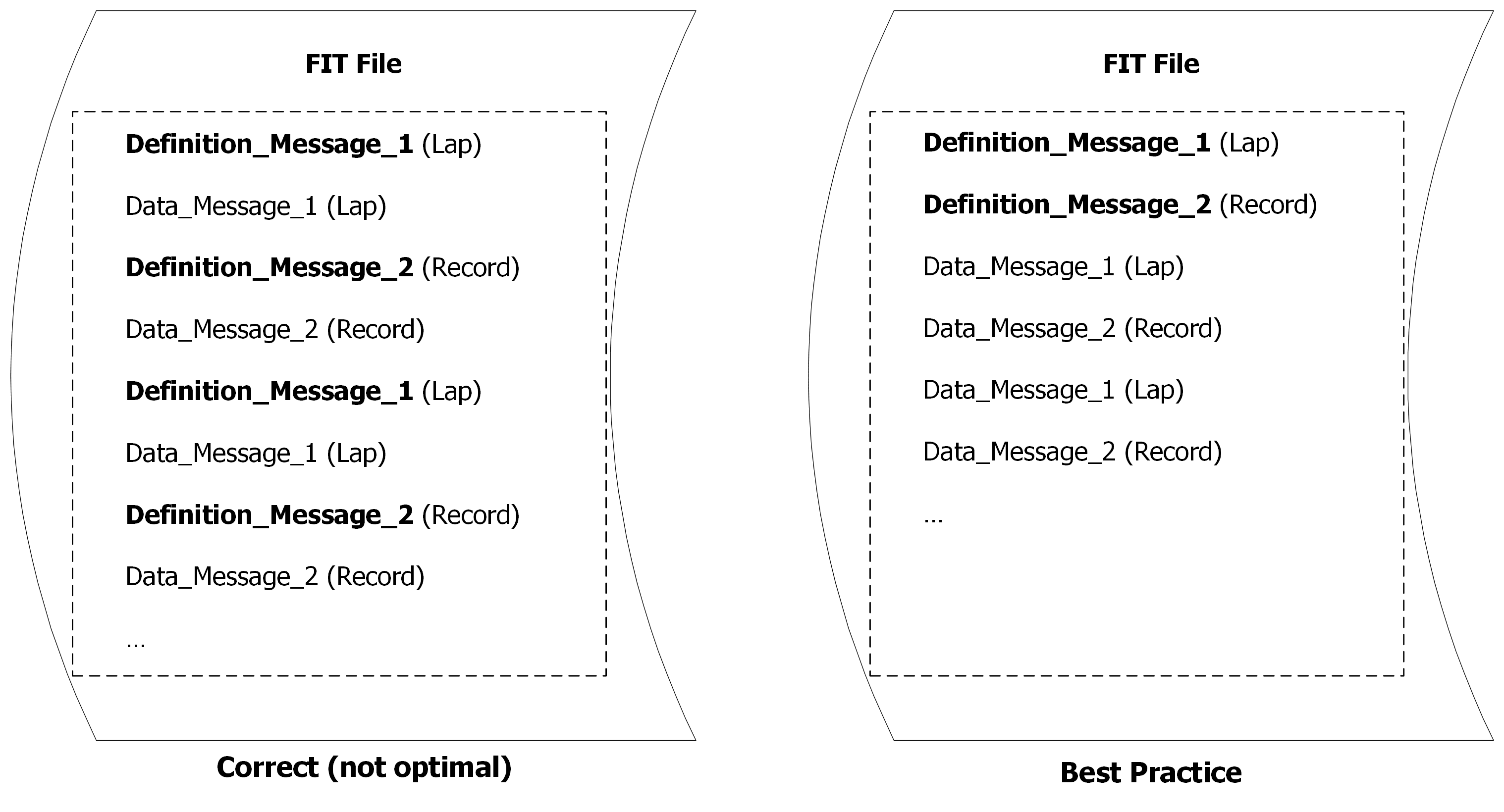
Often, multiple data messages of the exact same format are recorded. In this case, it is best practice to use a single definition message for all data messages; rather than recording a definition message for each data message. For example, in Figure 18, two types of data messages are being recorded: lap and record messages. The FIT file on the left contains a definition message for each data message. Although technically correct, this method of recording data is sub optimal; instead, define the lap and record messages once at the beginning of the file, followed by all lap and record messages as shown in the FIT file on the right.
Local message types can be redefined within a single FIT file. Figure 19, for example, shows a FIT file using a single local message type (i.e. 0) to record both the ‘file_id’ and ‘record’ data. Note that this FIT file contains the same data that is shown earlier in the FIT File Example. The number of local message types used in a file should be minimized in order to minimize the RAM required to decode the file. For example, embedded devices may only support decoding data from local message type 0. The advantage of using multiple local message types is the file size is optimized because new definition messages are not required to interleave different message types. Multiple local message types should be avoided in file types such as settings where messages of the same type can be grouped together.
Care must be taken when redefining local message types. If data message formats are recorded without the new definition message, unpredictable results will occur and may cause the decoder to fail.
Reference C, C++, C#, and Java code for both embedded and PC conversions of FIT files are available in the downloadable SDK. The FIT protocol is fully backwards compatible, ensuring that devices with different versions of the FIT protocol can share files. The conversion tool handles all conversion-related issues such as differences in device architecture (big endian vs. little endian), and differences in messages between devices which have different versions of the FIT protocol.
Figure 20 takes the example shown earlier in FIT File Example and shows how an incoming message is encoded according to the device’s implemented Product Profile and added to the FIT file. In this case, the data corresponding to Record 5 of the previous example is used.
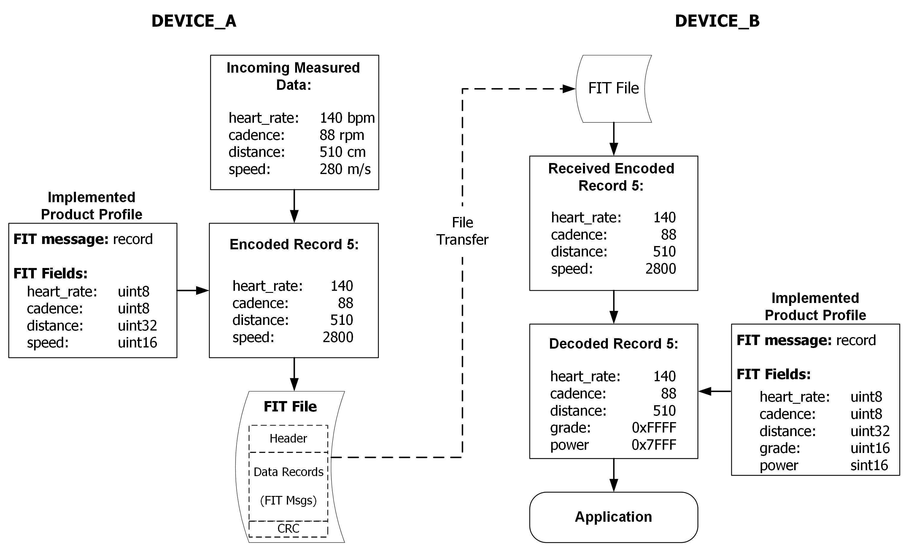
In this simplified example, Device_A’s implemented product profile includes the FIT ‘record’ message and its heart_rate, cadence, distance, and speed FIT fields. The incoming data is formatted and encoded according to the product profile and added to the FIT file. When all records have been added and the FIT file is complete, it is ready for transfer.
Device_B, on the other hand, has a slightly different implemented product profile that still includes the FIT ‘record’ message; however, this profile has a different set of FIT fields defined. Device_A and Device_B both have the heart_rate, cadence, and distance FIT fields, but Device_A includes speed, whereas Device_B includes grade and power data. As FIT is fully compatible across different versions of global and product FIT profiles, the protocol will automatically account for these differences.
As illustrated in Figure 20, Device_B receives the FIT file, and the decoder will interpret and decode the information it recognizes (i.e. heart_rate, cadence, distance), ignore data it does not recognize (i.e. speed), and populate the remaining FIT fields with invalid values according to its base type (i.e. grade and power). In this way, the FIT file is maintained and can be transferred again in its original form, unrecognized or missing data is processed by Device_B without causing errors, and the resultant information is passed in the form of a C structure or object to Device_B’s application for further use.
The FIT protocol is designed for extensibility. The software development code provided is designed to maintain compatibility as FIT files are transferred between systems. For compatibility between systems to be maintained, the FIT profile must be strictly adhered to. There is built in flexibility for system architectures. Endian architecture is described in each message definition and automatically handled within the FIT SDK.
Certain applications of FIT files lead to a natural grouping of messages based on purpose. Refer to the FIT File Types Description document for more details on the common message groupings and methods for best practice of the following file types:
Table 13. Common FIT File Types
| FIT File Type | Purpose |
|---|---|
| Settings | Describes a user’s parameters such as Age, Weight, and Height |
| Activity | Records data and events from an active session |
| Workout | Records data describing a workout’s parameters such as target rates and durations |
| Blood Pressure | Provides summary data from a blood pressure device |
| Weight | Provides summary data from a weight scale device |
Version 16.30 of the FIT SDK introduced a plugin framework that allows for the manipulation FIT files before the output is pushed to the end-application. This allows for the pre-processing of messages before the consumer of the data receives messages and definitions in its listener call-backs.
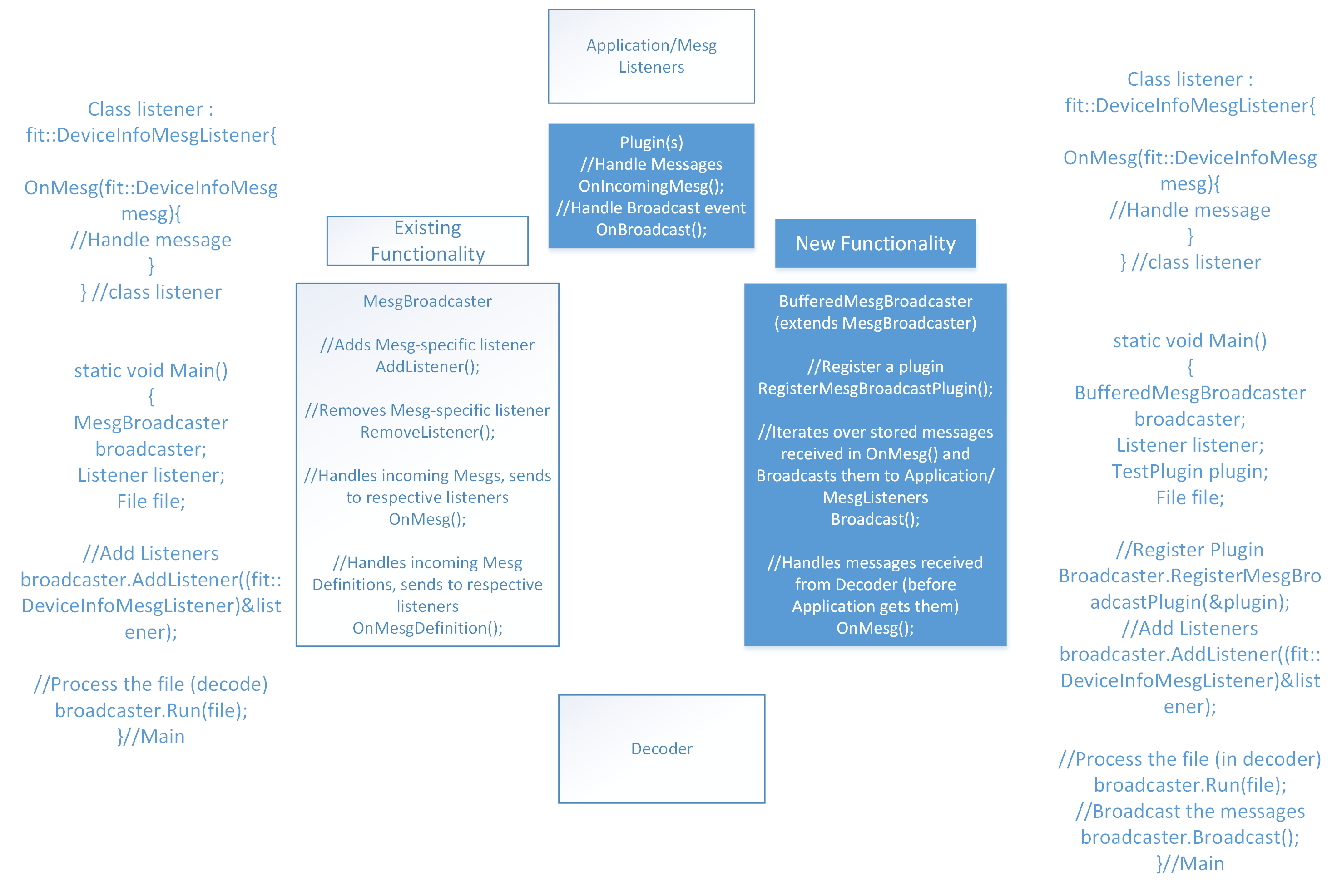
The plugin architecture allows for developers to perform pre-processing on FIT data before the final output is returned to the application’s subscribed listeners. A new MesgBroadcaster was created called the BufferedMesgBroadcaster which receives the messages from the decoder as they are processed by invoking the Run() method. Multiple plugins can be registered to a BufferedMesgBroadcaster and when messages come in they are dispatched to the OnIncomingMesg() handler in the plugin. Once the decoder finishes the Run() function completes. The consumer application will then call the Broadcast() method on the BufferedMesgBroadcaster. The broadcast method causes the plugins to process each individual message and once processed they are sent to the application’s registered listeners.
The plugin framework is implemented in C++, C#, and Java with very similar Application Programming Interfaces. The SDK includes the "Heart Rate to Record" Plugin which allows applications to process Garmin’s HRM-Tri "hr" messages and appends the heart rate values into the appropriate record message.
Below is a block diagram below that shows the functional pieces that were introduced in the SDK to support plugins and the differences needed in the application code to get started using plugins. The example is based on the C++ implementation.
The Heart Rate to Record Plugin was created to parse Compressed Heart Rate data into many record messages. It takes a message like:
Hr Mesg:
And converts it into multiple record messages shown below:
The plugin pre-processes all of the HR messages in a file, and maps the timestamps back to record messages and adds the heart rate values to the appropriate record messages.
Input:
Calibration message:
Data message:
Calibration Adjustment:

*Note that the orientation matrix is a row major representation of a three by three matrix
Output:
The Three D Sensor Adjustment Plugin does the calibration adjustment and adds the calibrated values to the data message under the appropriate fields.
Example:
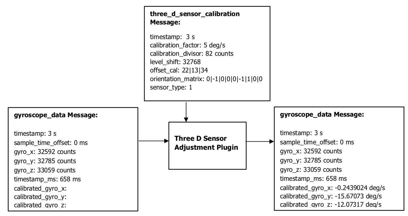
The Three D Sensor Adjustment Plugin was created to adjust the X, Y, and Z data points generated by the sensors (Accelerometer, Gyroscope, and Magnetometer) and convert them to the desired units. It takes messages that look like:
three_d_sensor_calibration Message:
gyroscope_data Message:
And alters the data message to look like:
gyroscope_data Message:
Figure 23 shows the flow of input and output messages through the Three D Sensor Adjustment Plugin.
| Revision | Effective Date | Description |
|---|---|---|
| 1.0 | May 2010 | Initial Release |
| 1.1 | March 2011 | Updated License |
| 1.2 | April 2011 | Updated File Header InformationCorrected Compressed Timestamp header description |
| 1.3 | April 2012 | Corrected minor errors in documentation (omissions, typos, incorrect data) |
| 1.4 | February 2013 | Updated templateUpdated agreementClarified global profile usageClarified FIT basetype definitions |
| 1.5 | February 2014 | Clarified ArraysClarified SubfieldsClarified Common FieldsUpdated template |
| 1.6 | May 2014 | Clarified Components |
| 1.7 | August 2014 | Clarified Scale/Offset Usage |
| 1.8 | October 2015 | Added chained FIT filesAdded Plugin Framework |
| 1.9 | April 2016 | Added Developer Data |
| 2.0 | May 2016 | Release for FIT 2.0Corrected Errors in Developer Data |
| 2.1 | June 2016 | VirbX PluginCorrected some Typos |
| 2.2 | August 2016 | Add Invalid Values for 64-bit integer typesAdd Description of Native Overrides in Developer Data |
| 2.3 | November 2016 | Clarify Native Overrides in Developer Data |
| 2.4 | March 2019 | Remove 255 byte message size limitation |